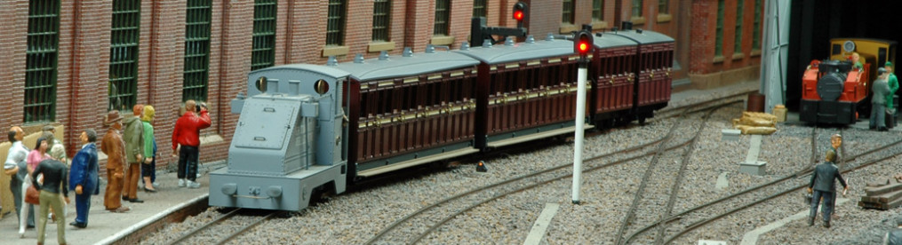
I’ve had one of the first Wrightlines ‘spud – u – like’ motor bogies for a long time which I used to write a review for the 7mm NGA magazine ‘Narrow Lines’ way back. As my O14 layout ‘Tony’s Forest’ started to come together I thought I should put a body on it. I have had a Nonneminstre Battery Mine loco body for a similar length of time, so I thought I would put the two together and this is now part of the Battery Mine Loco page.
My stock of kits is a bit like fine wine – they have to mature for a considerable length of time before use!
I have all of the Nonnemistre kits in a build queue with the Hudson-Hunslet next.
The Hudson may be on another Wrightlines bogie – I bought enough to do the three Nonneminstre kits some years ago in anticipation of the O14 layout.

Component parts of the motor bogie kit
This time however, I have departed from the standard Wrightlines instructions as I wanted to solder two lengths of ‘L’ section brass towards the top of the chassis block to locate on the footplate. This prevented the fitting of the pick-ups at the top (as originally designed) so I have moved them lower down. The still seem to work as intended, in fact this chassis runs a bit better than the battery mine chassis!

Modified bogie with ‘L’ section strips soldered near the top upon which sits the body. The pick-ups had to be mounted lower down but work just as effectively.

Footplate fitted and gearbox placed on top of the motor.

Progress to date. The cab front and sides needed some slight adjustment to suit the slightly higher protrusion of the motor bogie above the footplate.
The body needed some small adjustment as the top of the motor bogie sits a bit higher than the Tenshodo SPUD unit for which the kit is really designed. Body assembly will follow the instructions although I may choose to fix the motor bogie top cover to the body rather than to the bogie itself.
I haven’t decided whether to use this bogie yet as since I started the project Mark Clarke (Locos n stuff) brought out an etched Universal Power Bogie which has a better gear ratio and will fit under the two remaining body kits that I have. I may try both to see which one I prefer, though I suspect (purely on control-ability) that it will be the Locos n stuff bogie.
The Wrightlines bogies are a bit of a fiddle to put together to achieve good running and there isn’t much that you can do about the low gearing or motor characteristics. The axles are retained by a whitemetal keeper which is screwed at either end. This is prone to bending and can result in poor meshing of the gears. Although I have a number of these in my stash, I am not sure if they will be built as there are now better alternatives available like the Mk2 SPUD replacement from Locos n stuff.
Fast forward to 2026. I have been thinking for some time on a 014 SPUD replacement.


My modelling is basic and somewhat agricultural but I have found a combination table invaluable when needing to get an accurate wheelbase. In this case 3mm up from the bottom of the 10mm wide brass strip and 26mm wheelbase.
Why build my own SPUD replacement when you can get them from Locos n stuff? Well, those chassis are 3d printed and have fairly wide ends so tend to be longer than a Tenshodo SPUD. Some of my projects need something closer to the length of the Tenshodo versions. The intent is to have better control within the space envelope of a Tenshodo SPUD (and to 14mm gauge too).

If I have calculated things correctly then I can use Mod 0.3 20 tooth gears and still get close to the required height of the chassis. To do this, I need to use 9.5mm wide spacers using the axle holes to hold the frames apart so that I can solder on ends and a plate underneath. The motors are Tramfabriek 8mm diameter by 16mm long which fit nicely between my frames, spaced at 9.5mm (the length of my Markits spacers!).

As I said earlier, all very basic and agricultural!

The axle holes were opened out for top hat bearings before cleaning up and test fitting the axles.
The intention is to pack up from the bottom plate to support the Tramfabriek 8mm diameter double shaft motor. The worms will stay below the frames so there should be enough room to accommodate them in the 3d printed body this chassis is intended for. There is packing from the central baseplate to support the motor and 20 thou plastic sheet either side to centralise the motor.
For a WDLR Tin Turtle that was modified for an early Locos n stuff chassis, I think I can use 28 tooth Mod 0.3 gears and just stay within the height.
This is the initial proof of concept run and I need to come up with something better than Bluetak to hold the motor in place. Probably silicon sealant.
The chassis runs a lot quieter than the original locos n stuff one.

This is the prototype drive unit and it was possible to get 28 tooth Mod 0.3 gears in the available space. The limiting feature is the distance from the axle to the end of the chassis and the clearance of the worm to the body. The wheelbase is 28mm to suit the Wrightlines WDLR “Tin Turtle”. The body was originally adjusted to suit the Locos n Stuff chassis but it was noisy and the very small motor was not really powerful enough for the heavy body.

Also, in progress are 26mm and 24.5mm wheelbase versions. I messed up the drilling of the 24.5 version so started again from the other side, hence the extra holes!

These have 20 tooth Mod 0.3 gears as I need the worms to sit below the top of the frames and give enough clearance for the 16mm long motor. I could probably get away with 22 tooth or 23 tooth gears on the 26mm chassis but I haven’t got any of those.

The 24.5mm wheelbase chassis will go under the Nonneminstre battery loco and replace the speedy Wrightlines chassis.
My attempt at fixing the motor in place with silicone was not successful as it had too much “give” in it. So I took a deep breath and glued the moor in with epoxy adhesive. This makes it almost impossible to remove the motor but I have to admit that I haven’t needed to replace many motors over the years, so I will live with this. It helps packing the motor up from the base so that the mesh is acceptable. A bit of trial and error as you can’t easily see the mesh, all I could do was check the gears moved a bit when the motor was held in place.
One thing I never thought about was the relationship of the worms to each other on the motor shaft. It either doesn’t matter or I have been lucky. I think in future I will fix one worm first, then position the other worm while holding the motor in place before fixing the worm.
Here is the first test run of the Wrightlines WDLR Simplex with the motor permanently fixed:
I have to admit that I am really pleased with the running, however, Things that run successfully on my test track don’t always do the same on the layout! I will be able to test this at the next show which is at Northampton.
Flushed with success, here is the first test run of the Nonneminstre battery loco:
It is not quite as good as the Simplex but still a vast improvement over the original chassis. It has a gear ratio of 20:1 so it is better than the original 14:1 Tenshodo gears. Coreless motors tend to run faster but these from Tramfabriek have very good slow speed characteristics too. Again, it will be interesting to see if the loco performs reliably on the layout.

Finally, a view of the underside of the Nonneminstre battery loco showing the very limited clearance from the axle to the driver’s footwell. This was the instigator for creating the design of the drive as there wasn’t room for the large block of 3d printed chassis associated with the Locos n stuff chassis.
I had the opportunity to test my new drives at the Northampton show on the 18th July 2026 and I must admit that I am extremely pleased with their performance. Not surprisingly, the longer wheelbase 28:1 gear ratio drive performed better than the short wheelbase 20:1 gear ratio drive. However, the 20:1 drive ran beautifully and is a testement to the quality of the Tramfabriek motors.
I have a few other locos that would benefit from these replacement drive units and I can see that I will be building a few more in due course.