Track, Signals & Electrics
Being awkward, I wanted to portray both the original lightweight track of the factory system and the heavier-weight track of the new passenger-carrying railway, so I decided to build my own track using copper-clad circuit board. Suitable strip was purchased from the 7mm NGA Sales Department – which has proved a very useful source of bits and pieces for the whole layout. PECO code 82 flat-bottomed rail was used for the original factory track and code 100 flat-bottomed rail was used for the new passenger carrying line (again from PECO). At this stage, Roger Brown (of Syreford, see the April 1999 BRM) volunteered to build the points, an offer that was very gratefully received as I was running out of time! A sub-base of 3mm thick cork floor tiles was glued to the ply baseboard surface in an attempt to gain quieter running. This was glued down with the proper cork tile floor contact-adhesive, which worked much better than white pva. With the points in place, half-track sections (ie one rail soldered to a run of sleepers) were aligned and pinned in place with drawing pins. The other rail was soldered on using track gauges to hold it in the correct position. The finished sections were lifted and scrubbed clean to remove all traces of flux before being spray painted a muddy grey-brown colour. Dropper wires for the different sections were soldered onto the underside of the rail and threaded through pre-drilled holes in the baseboard. These were invisible once the track was ballasted. The points were connected up to Lemaco motor units, which were bolted through the baseboards – fixing them was a problem that I had not envisaged when I though of using 6mm plywood for the baseboards! New operating wires were bent up, as I wanted to hide the drive under either point motor boxes for the new track or hand levers for the old track. I’ve not had any problems with the point motors (so far – touch wood!) but a long vertical length of operating wire was required, which acts as a significant torsion spring, and requires very free moving point blades. The track sections were glued down with white pva before ballasting – I like to test out the running before I ruin it with ballast!

This guy has been shoveling sand for ages!
I wanted colour light signals to suit the modern-image and used 4mm scale Eckon signal kits, substituting longer poles to suit. These are interlocked to the points to ensure that you only get a green light if you have set the route. The signal into the station from the fiddle yard is the master – if this is green all the others can only be red. The signals are also interlocked to the track, giving a dead section if they show a red light.
The dropper wires from the track sections are connected locally under the baseboard to “chocolate-block” connectors. Colour coded wires feed the individual sections back to solder tags, which are connected to computer type “D” multi-pin sockets. There is a socket on each of the three scenic boards fed by an individual cable from the control panel so each board can be tested individually. I have probably gone in for “over-kill” on the electrics as I am paranoid about problems at a show, which I can’t fix. I like the security the separate cables and plugs give – they can’t be snagged or damaged if they are packed away for transport (I hope – but they can be lost!). The track is wired for twin-controller “cab control” using double-throw centre-off section switches. Signal logic is controlled by contacts on the point motors and relays (it has to be simple for me to have worked it out!). The signal/track dead sections use diodes to allow trains to pass the signals from the other direction. Wiring has been kept as neat as possible under the baseboards and cable-wrapped or bundled with cable ties where possible.

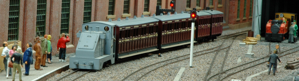
Teddy brings in an empty works train
The control panel is carried separately and bolted to the layout when in use. I had originally envisaged building it into the centre scenic board but could not find enough room. The panel has the track circuit marked on it identifying all the section, point and signal switches. Plug-in “wander” controllers from Modellex are used as they are suitable for all motor types and give excellent control for slow running or shunting. A small socket is also provided for a wheel-cleaning brush made up from a brass-bristle suede shoe brush. Power is supplied from a separate floor-mounted transformer box through heavy-duty 8-way ‘Bulgin’ plugs and sockets. This keeps all the mains electricity away from the baseboards and operating area.
The track was thoroughly tested to confirm that everything worked as it should and that all the rolling stock ran reliably. I then decided that the track looked a bit plain and experimented by adding rail spikes to a short section. This convinced me that the whole layout had to have rail spikes – I only needed to drill every sleeper at least four times with a 0.7mm drill and insert the ‘Roy C Link’ spikes! It took a while (seemed like forever at the time) but it was well worth it and people often comment on my use of PECO track! Rail and spikes were painted a variety of rust colours and the sleepers were weathered with washes of greys and browns before being ballasted with ‘GreenScenes’ ballast. This was laid down dry and pushed into place with an old paintbrush before being soaked in diluted white pva (with a drop of washing-up liquid in it to reduce the surface tension). The track was tested again to check that the ballasting had not introduced any problems before the more general scenic work was added.
The story continues on the Buildings, Scenery & Details page.
Click here to return to the main Ashcross page.