Black Dog Mining O&K:
With my apparent lack of finishing locos, I grabbed the opportunity to buy two read-built locos when advertised on the NGRM Forum.

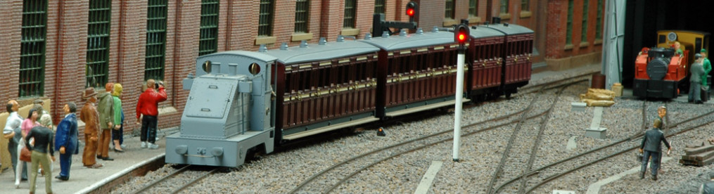
One of these (the yellow loco in the middle) is a cast resin O&K diesel body from Black Dog Mining on a KB Scale chassis. It had an exquisite yellow paint finish with beautiful black ‘wasp’ stripes on the ends. The driver wasn’t so well painted but as he (or rather his seat) had fallen off, it was a simple task to repaint him. The resin body was a bit light so I packed as much lead as I could into any available space, including the chassis to help improve the running. The loco ran nicely on the test track but was not so good on the layout and needed the wheel back-to-back reducing a bit. However, at this point I found that there was insufficient clearance left for the wheels and when the appropriate back to back was set, the wheels were too tight against the chassis for smooth running. With space so tight I wasn’t sure how to remove the wheels without damage to either them or the chassis.
I elected to replace the chassis with one of the 3d printed ones designed and used by Tim Crockford. This used 9.5mm diameter wheels from Mark Clarke (Locos n stuff) and is a very smooth runner and solved my gauge problems. However, with such a small body made out of resin, there is very little space for weight and its running is not as reliable as I would like on my track work (which leaves a lot to be desired).
Nonneminstre O&K:
The second loco was a Nonneminstre O&K diesel with a mediocre paint finish on both the body and the driver. I used some light washes to repaint the body in an attempt to give it a faded and distressed look. The driver was a bit harder to paint as he was firmly glued in position. This is a very noisy loco, particularly in one direction but it does run smoothly and being whitemetal is nice and heavy, so it is more suited to my track work.
It was only when I had built my own version of the Nonneminstre kit that I realized both seat and driver had been mounted the other way around on the second-hand model. The second-hand model had a new copper clad keeper plate fitted for the pick-ups but I found that there was enough room for some thin copper clad pads and phosphor-bronze strip to mount on the side of the chassis block for my own model. My kit was built as per the instructions although I realized afterwards that I had got the axle boxes the wrong way around – despite my best efforts! Luckily I found a photo of one in Germany with the same axle boxes, so I have proof that they got it wrong in real life too!
Hesketh Models O&K MD2:
I think I bought this Hesketh Models O&K in 2015 – at least that’s the date on the instructions!

I started it fairly early on but for some reason set it to one side. I probably moved on to building the layout and then stock that could be finished quickly in time for the first show!
At the end of 2025 it finally made its way up the build pile to the point where I thought “how far did I get with it?”. Turns out I got as far as the chassis and folding up some of the body parts.

The drive is from a vertical motor onto a large worm and gear. I blackened the steel worm to try to hide it a bit.

4 wheel drive is achieved by an ‘O’ ring and two pulleys. The gear wheel has a grub screw so I soldered the pulley onto it. I found that a cocktail stick was about the right diameter and forced it into both gear and pulley, giving good alignment. This means that that axle can be dismantled if I need to replace the ‘O’ ring. My thoughts turned to the other pulley and I found an old gear wheel with a grub screw that I soldered to the pulley using the cocktail stick for alignment.

The body parts are very finely etched and go together well. They are just balanced in position for these photos to help me check if I can fit an albeit small flywheel and yes I could.

Castings are in resin so are light weight, however there is quite a bit of space ahead of the motor and a bit at the back of the chassis. A white metal driver and some lead should enable enough weight and keep it in balance. At this point it ran nicely in one direction and noisily in the other. There appeared to be quite a bit of end float in the motor which was reduced with a thrust washer.
The wheels looked to be nickel-silver and solid on one side, insulated on the other. The solid ones needed soldering to the axles and I used some scrap pieces of wood to get the right axle protrusion. The flanges looked a little thick and I had to close up the back-to-back to about 12.1mm. This was very close to my check rail clearances so I decided to replace them with finer wheels.
The motor was okay when just driving the single axle and ran okay-ish when the belt was fitted but got very hot. I suspected it was struggling with the resistance from the belt. I tried a thinner belt which improved things a bit.
I had not been happy with the running of the original chassis. A combination of lowish gearing and belt drive was making it hard to start slowly or shunt. I thought about a replacement chassis and came up with something that might work, albeit with a few complications! After all, why make things difficult when with a little bit of effort you can make them virtually impossible!
So I set about a simple chassis where the 9.5mm Markits spacers could also carry a layshaft for the gears.

The spacers had to be far enough away from the wheels to not be in the way which meant that some additional sleeves would be required to limit end float of the worms.


The fit and space available for the motor meant the pulley for the belt drive would be trapped making belt replacement difficult.

So while one spacer is fixed, the other is removable to permit belt replacement.

A piece of brass strip was bent up and drilled to form the motor support.

Simple wiper pick ups were glued on and the frames painted.

I got a motor from Tramfabriek. In these photos it still needed the shafts trimming so it would fit in the body.

I think the running will improve with time and the addition of some weight.
I was hoping that I wouldn’t have to modify the footplate but I needed to trim a bit at the front. This removed the original front fixing but by that point I had enough confidence in my chassis now that I wouldn’t need to go back to the original chassis.

Progress was slow at the end of 2025 due to competing claims on my time but I did manage to assemble the basic parts of the body.

These parts are very accurately etched and went together very nicely. The chassis fitted too!

There should be enough clearance for the belt when the resin castings go on so it looked like I had more or less got the motor mounting plate in the right place.
Whilst the kit is beautifully etched, a number of the small parts, like the gear change mechanism, proved very challenging to my fingers and eyesight! The body has been finished to the best of my ability and runs nicely on the test track. It will need to be tested on the layout at an exhibition before I will know if the revised chassis design has worked.

Since the above photo, I have added couplings and it has become part of the stock during the 2026 show season. It performed very nicely at its first show at Alton in February 2026 and I am very pleased with it.